Why PCB Traces Should Avoid 90-Degree Angles?
Date:2024-11-28 10:42:02
In electronic device design, PCB (Printed Circuit Board) layout plays a crucial role in determining product performance and reliability. Among the many considerations in PCB design, avoiding 90-degree angles in traces is a widely recognized guideline. This principle is not merely about aesthetics; it is rooted in concerns about electrical performance, manufacturing processes, and overall product reliability. In this article, we explore why PCB traces should avoid 90-degree angles, focusing on electrical performance, signal integrity, EMI (Electromagnetic Interference), manufacturing processes, and heat dissipation.
Electrical Performance Issues
1.1 Impedance Matching Problems
In high-speed circuits, signal traces exhibit a specific characteristic impedance (typically 50 ohms or 75 ohms). A 90-degree turn causes a sudden change in trace width at the corner, resulting in impedance discontinuities. These discontinuities can lead to signal reflections and losses, impairing circuit performance.
1.2 Current Concentration Effects
Current tends to concentrate at the corners of a 90-degree turn, especially in high-speed signals. This concentration can increase losses at the corner, reducing circuit efficiency.
Signal Integrity Issues
2.1 Increased Reflection and Crosstalk
A 90-degree angle alters the signal transmission path abruptly, causing electromagnetic waves to reflect at the corner. For high-speed digital signals, these reflections can distort signals and degrade their quality. Additionally, sharp turns may exacerbate crosstalk, disrupting the stability of nearby traces.
2.2 Edge Effects
Sharp corners in PCB traces disrupt the electromagnetic field distribution, generating unwanted high-frequency radiation. This edge effect is a significant contributor to signal interference and electromagnetic compatibility (EMC) issues in high-speed PCBs.

Electromagnetic Interference (EMI) Issues
3.1 Generation of High-Frequency Noise
Sharp corners can act as "antenna points," emitting high-frequency noise and degrading the PCB's overall EMI performance. This noise can interfere not only with the circuit itself but also with other nearby electronic devices.
3.2 Increased PCB Radiation
In high-frequency circuits, the corners of signal traces can become sources of electromagnetic wave radiation, raising the PCB's overall emission levels. This can lead to compliance issues during EMC testing and real-world operational problems.
Manufacturing Process Issues
4.1 Chemical Corrosion Risk
During PCB manufacturing, chemical solutions can accumulate at sharp corners, increasing the risk of corrosion. This issue is particularly significant in multilayer boards, potentially compromising the long-term reliability of the PCB.
4.2 Photolithography Errors
90-degree corners can create "sharp edge effects" during photolithography, causing the copper at the corners to crack or remain incomplete. This can reduce the overall quality of the PCB.

Heat Dissipation Issues
5.1 Local Overheating Risk
The abrupt change in trace width at a 90-degree corner concentrates current density, which can lead to localized overheating. This problem is especially critical in high-power circuits, where effective heat dissipation is essential.
Alternative Design Approaches
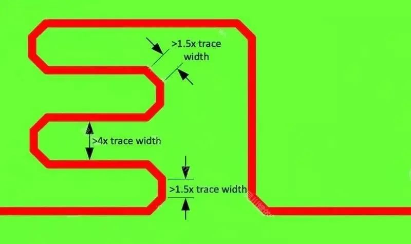
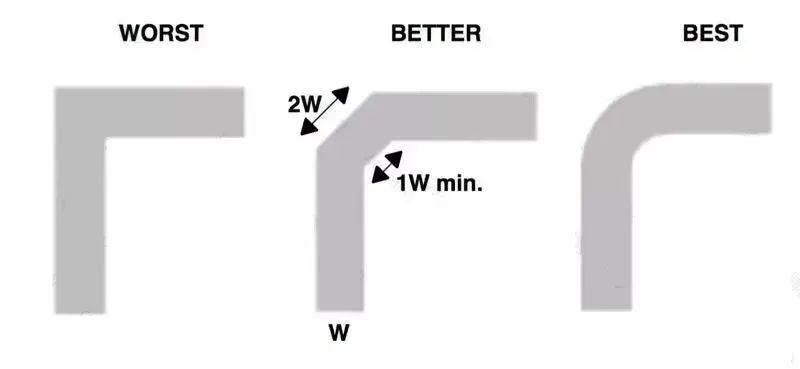
6.1 Using 45-Degree Angles
Engineers commonly replace 90-degree turns with 45-degree angles. This design reduces impedance discontinuities, minimizes signal reflections, and improves signal integrity.
6.2 Curved Traces
For high-speed or RF circuits, curved traces are a better option. Curved traces improve impedance matching and significantly reduce EMI issues.
6.3 Optimizing Layout with Vias
In complex multilayer boards, vias can be strategically used to reduce the need for sharp turns and optimize signal routing.

Case Study Analysis
In a high-speed communication circuit, designers experimented with 90-degree turns and observed a decline in signal integrity along with increased high-frequency noise. Replacing the sharp turns with 45-degree angles or curved traces led to noticeable improvements in signal quality and a reduction in EMI issues. This real-world example underscores the necessity of avoiding 90-degree angles in PCB design.
Conclusion:
Avoiding 90-degree angles in PCB traces is a crucial design principle that addresses electrical performance, signal integrity, electromagnetic compatibility, manufacturing, and thermal considerations. Using 45-degree angles or curved traces can significantly enhance PCB performance and reliability. This design detail is especially vital in high-speed and high-frequency circuits. Engineers should thoroughly account for these factors in their designs to ensure product quality and stability. By understanding the importance of avoiding 90-degree angles, designers can optimize PCB layouts and create more stable and efficient electronic devices
