How to Understand the Characteristic Impedance of PCB?
Date:2024-09-20 14:49:58
1. What is characteristic impedance?
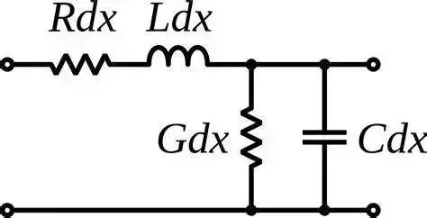
The characteristic impedance of a transmission line, also known as characteristic impedance, refers to the impedance per unit length of a transmission line when it propagates electromagnetic signals. Characteristic impedance is usually used to describe the characteristics of a transmission line. It is the sum of the resistance and reflection encountered by electromagnetic waves when propagating in the transmission line. In high-speed signal transmission application scenarios such as DDR, PCIE differential or SATA, signal transmission lines can no longer be regarded as ideal conductors, and parasitic parameters such as parasitic resistance, parasitic capacitance, and parasitic inductance need to be considered.
The transmission line of unit length can be equivalent to the following model:

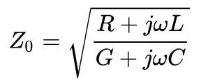
The impedance expression of this model is:

Theoretically, the exact characteristic impedance is a frequency-dependent quantity. However, in practical applications, the resistance of the transmission line, that is, the energy dissipation part, can often be ignored, that is, R and G in the above formula are 0. It is approximately a lossless transmission line.
For a lossless transmission line, the impedance expression can be expressed as:

Where L is the inherent inductance per unit length of the transmission line, and C is the inherent capacitance per unit length of the transmission line. This simple calculation formula shows that to change the characteristic impedance of the transmission line, the inherent inductance and capacitance per unit length of the transmission line must be changed.
PCB routing is often controlled at 50Ω, and the coaxial line impedance is 50Ω or 75Ω. Under inaccurate requirements, impedance is not related to frequency.

2. How to do impedance matching?
Impedance matching is a concept in microwave electronics. For transmission lines, it means that all high-frequency signals can be transmitted to the load point without any signal reflection. There are generally two ways to achieve impedance matching: changing the characteristic impedance (lumped-circuit matching) and adjusting the wavelength of the transmission line (transmission line matching). Changing the characteristic impedance can increase or decrease the impedance value of the load by connecting the capacitor or inductor in series with the load, and the corresponding impedance point will move along the impedance circle. Correspondingly, the characteristic impedance of the transmission line is adjusted by adjusting the capacitor and inductor to match the input impedance and the output impedance.
Adjusting the wavelength of the transmission line can be achieved by changing the length of the transmission line. For example, by increasing the length of the transmission line, the signal can experience more phase changes during transmission, thereby achieving impedance matching at a specific length. In practical applications, impedance matching can be performed by short-stub matching or quarter-wavelength impedance transformer.
Impedance matching results in high transmission power. For a power supply, when its internal resistance is the load, the output power is the largest, and the impedance is matched at this time.
Taking a broadband amplifier with an output impedance of 50Ω as an example, if maximum power transmission is required and the signal is not reflected, impedance matching needs to be considered. If the signal wavelength is much longer than the cable length, impedance matching does not need to be considered.
